Bryant Outdoor Heating Unit 379A User Manual

Browse online or download User Manual for Gardening equipment Bryant Outdoor Heating Unit 379A. Bryant Outdoor Heating Unit 379A User Manual

  • Download
  • Add to my manuals
  • Print
  • Page
    / 8
  • Table of contents
  • BOOKMARKS
  • Rated. / 5. Based on customer reviews
Page view 0
Installation Instructions
OUTDOOR HE ATI N G UNIT
379A
Models
48W- & 60W-379A
Series C
fariiant
Bryant Models 48W-379A and 60W-379A are outdoor
heating units designed for installation on a rooftop or
at ground level. Both models have a chilled water coil
factory installed. Model 48W-379A is equipped with a
48.000 Btuh coil while Model 60W-379A is equipped
with a 60,000 Btuh coil.
These units were designed for use in split systems with
matching Bryant gas-fired water chillers. Both models
have 150,000 Btuh heating input rating and a 112,500
Btuh heating output rating. Model 48W-379A has a
48.000 Btuh cooling rating when connected to a
Bryant Model 48-453 Gas-Fired Water Chiller. Model
60W-379A has 60,000 Btuh cooling rating when con
nected to a matching Bryant Model 60-452 Gas-Fired
Water Chiller.
Important—Read before Installing
1. Check all local or other applicable codes for in
formation concerning proximity to property lines,
height above roof, obstructions, etc.
2. Be sure the power supply available (voltage,
frequency, and phase) corresponds to that specified
on the unit rating plate.
3. Check the electrical service provided by the utility
for the building to be sure that the service capacity is
sufficient to handle the load imposed by this unit.
4. Refer to the regulations of the serving gas supplier
and the local building, heating, plumbing, or other
codes in effect in the area in which installation is to
be made.
5. Refer to the dimensional drawing on page 2 for
location of electrical, gas, and chilled water con
nections prior to setting the unit in place.
GENERAL
The design of this unit is certified by A.G.A. for use
with natural or propane gases with appropriate con
trols and orifices. This unit is designed for outdoor in
stallation only.
Installation of the unit consists of the following:
I. Locating the Unit
II. Gas Piping
III. Duct Connections
IV. Venting
V. Coil Connections
VI. Electrical Connections
VII. Start-up and Adjustments
I
39379D36
4/15/72
I i
L<-:
I.DO
’REMOVc- '
Figure 1—Model 48W-379A
In addition, the following section should be reviewed
by the equipment owner.
VIII. Maintenance
I. LOCATING THE UNIT
Extreme caution should be used when rigging and
moving the unit to prevent damage. The unit should
be kept upright during all rigging and moving
operations. To facilitate lifting and moving, place the
unit in an adequate sling made of rope or cable.
CAUTION: Be sure to protect the top and sides of the
unit from cable damage when rigging the unit to be
lifted.
Rooftop Installation
Level the unit on a base that is at least 6 inches above
the roof to provide drainage from beneath the unit.
Consult local codes for installation requirements. Be
sure that the roof will support the additional weight.
Ground Level Installation
If the unit is to be installed on the ground, it should
be placed on a level concrete slab with a minimum
thickness of 4 inches.
Page view 0
1 2 3 4 5 6 7 8

Summary of Contents

Page 1 - Installation Instructions

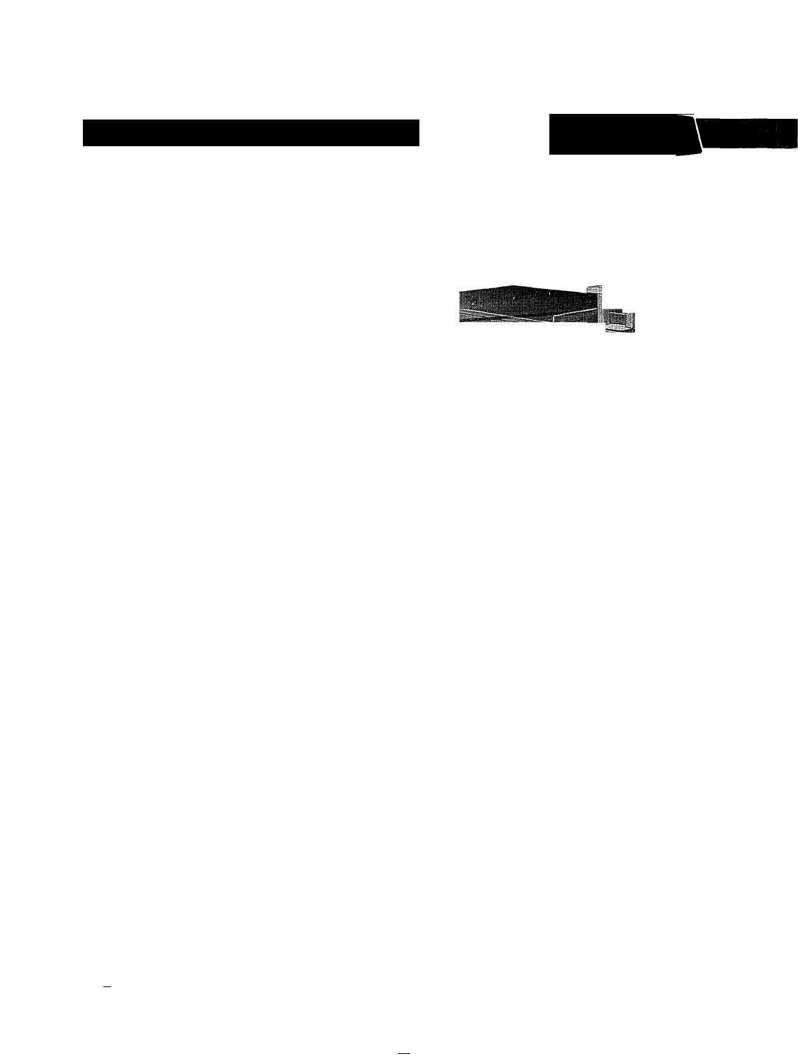
Installation InstructionsOUTDOOR HE ATI N G UNIT379AModels48W- & 60W-379A Series CfariiantBryant Models 48W-379A and 60W-379A are outdoor heating

Page 2

1 FP.T. WATER CONNECTIONS-GAS CONNECTIONLINE VOLTAGE LOW VOLTAGERETURNAIRLEFT SIDEFRONT RIGHT SIDE4314 IH*'...M223| H irIN=16&ap

Page 3 - Figure 3—Drip Leg Location

NOTE: It is important that the unit be installed in a level position.ClearancesThe rm'nimmn clearance is 6 inches from the duct side, 24

Page 4 - VI. ELECTRICAL CONNECTIONS

Figure 4—Mounting Air Shroud on Propane UnitAn air shroud is also shipped with propane units only. Install these items as follows:1. Remove the cov

Page 5 - — 5 39379D36

local code governing such wiring. Field low voltage connections are to be made in accordance with the wiring diagram shown in Figure 8.

Page 6

Adjusting Gas InputThe gas input must be checked and adjusted, if necessary, to agree with that shown on the unit rating plate (150,000 Btuh).

Page 7

and turn gas pressure adjusting screw counterclockwise.Checking Propane Gas input The burner orifices are sized for rated input with

Page 8 - Model 60-452 Chiller

CONTROL BOXCONTROL BOXA72163Figure 8—Connecting Modei 48W-379A to Modei 48-453 Chiiier or Connecting Model 60W-379A to Model 60-452 Chiller.39379D36-8

Comments to this Manuals

No comments