2. Firmly touch a clean, unpainted, metal surface of the
furnace chassis which is close to the control. Tools held in
a person’s hand during grounding will be satisfactorily
discharged.
3. After touching the chassis you may proceed to service the
control or connecting wires as long as you do nothing that
recharges your body with static electricity (for example; DO
NOT move or shuffle your feet, DO NOT touch un-
grounded objects, etc.).
4. If you touch ungrounded objects (recharge your body with
static electricity), firmly touch furnace again before touch-
ing control or wires.
5. Use this procedure for installed and uninstalled (un-
grounded) furnaces.
6. Before removing a new control from its container, dis-
charge your body’s electrostatic charge to ground to protect
the control from damage. If the control is to be installed in
a furnace, follow items 1 through 5 before bringing the
control or yourself into contact with the furnace. Put all
used AND new controls into containers before touching
ungrounded objects.
7. An ESD service kit (available from commercial sources)
may also be used to prevent ESD damage.
INTRODUCTION
The model 331JAV Series B Furnace is available in sizes 60,000
through 100,000 Btuh input capacities.
The design of the downflow gas-fired furnace is A.G.A./C.G.A.
certified for natural and propane gases and for installation on
noncombustible flooring. The furnace is factory-shipped for use
with natural gas. The manufacturer’s accessory gas conversion kit
is required to convert furnace for use with propane gas.
These furnaces SHALL NOT be installed directly on carpeting,
tile, or any other combustible material other than wood flooring. In
downflow installations, the manufacturer’s accessory floor base
must be used when installed on combustible materials and wood
flooring. Special base is not required when this furnace is installed
on manufacturer’s Coil Assembly Part No. CD5 or CK5, or when
Coil Box Part No. KCAKC is used. This furnace is for installation
in alcoves, attics, crawlspaces, basements, closets, or utility rooms.
The design of this furnace line is not A.G.A./C.G.A. certified for
installation in mobile homes, recreation vehicles, or outdoors.
Before installing the furnace, refer to the current edition of the
NFGC and the NFPA 90B. Canadian installations must be installed
in accordance NSCNGPIC and all authorities having jurisdiction.
For a copy of the NFGC NFPA54/Z223.1, contact International
Approval Services U.S. Inc., 8501 E. Pleasant Valley Road,
Cleveland, OH 44131 or National Fire Protection Association Inc.,
Batterymarch Park, Quincy, MA 02269. For a copy of NFPA 90B,
contact National Fire Protection Association Inc., Batterymarch
Park, Quincy, MA 02269.
Before installing the furnace in Canada, refer to the current edition
of the NSCNGPIC. Contact Standards Department of Canadian
Gas Association, 55 Scarsdale Road, Don Mills, Ontario, Canada
M3B 2R3.
The duct system should be designed and sized according to
accepted national standards published by: Air Conditioning Con-
tractors Association (ACCA), Sheet Metal and Air Conditioning
Contractors National Association (SMACNA). Or consult the
Residential Systems Design Guidelines reference tables available
from your local distributor. The duct system should be sized to
handle the maximum CFM capabilities of the equipment at the
optimum design static pressure.
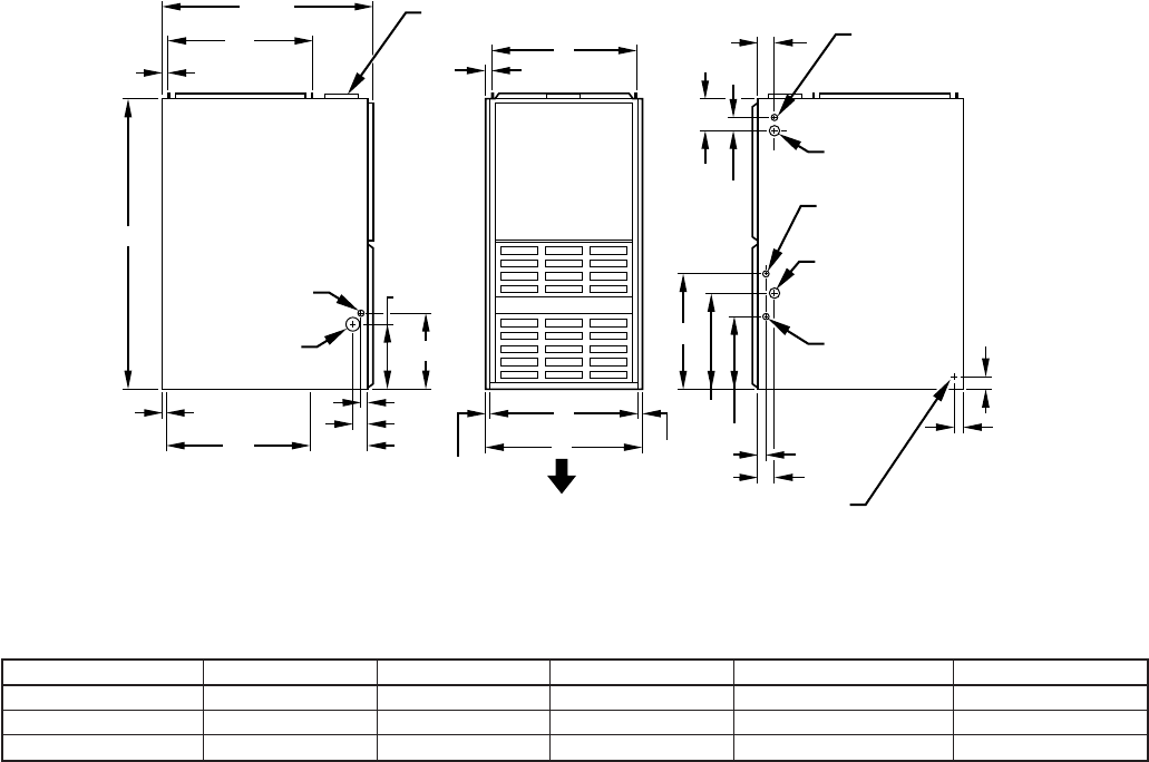
Fig. 1—Dimensional Drawing
A88324
4
3
⁄
16
″
2″
2
15
⁄
16
″
13
⁄
16
″
11
⁄
16
″
9
1
⁄
8
″
10
1
⁄
4
″
1
1
⁄
16
″
2
1
⁄
8
″
8
1
⁄
4
″
10
1
⁄
4
″
1
1
⁄
16
″
2
1
⁄
8
″
16
1
⁄
16
″
13
5
⁄
16
″
19″
11
⁄
16
″
13
⁄
16
″
11
⁄
16
″
20″
28
1
⁄
2
″
39
7
⁄
8
″
D
5
⁄
8
″ TYP
1
″ TYP
E
A
AIRFLOW
OUTLET
INLET
1
⁄
2
″ DIA
THERMOSTAT
WIRE ENTRY
7
⁄
8
″ DIA
ACCESSORY
7
⁄
8
″ DIA
ACCESSORY
DIMPLES TO DRILL HOLES
FOR HANGER BOLTS (4 PLACES)
IN HORIZONTAL POSITION
ADDITIONAL
7
⁄
8
″ DIA K.O. ARE
LOCATED IN THE TOP PLATE
AND BOTTOM PLATE
NOTE:
7
⁄
8
″ DIA HOLE
POWER ENTRY
1
1
⁄
2
″ DIA
R.H. GAS ENTRY
7
⁄
8
″ DIA
ACCESSORY
1
3
⁄
4
″ DIA HOLE
GAS ENTRY
VENT CONNECTION
TABLE 1—DIMENSIONS (IN.)
UNIT SIZE A D E VENT CONN SHIP. WT
036060 14-3/16 12-9/16 12-11/16 4 145
048080 17-1/2 15-7/8 16 4 154
060100 21 19-3/8 19-1/2 4 181
—2—
→
 (44 pages)
 Manymanuals.com
 Manymanuals.de
 Manymanuals.fr
 Manymanuals.it
 Manymanuals.pl
 Manymanuals.cz
 Manymanuals.es
 Manymanuals-pt.com
Comments to this Manuals